Animating locomotive rods
This guide is authored by Voxel Tycoon community member scailman
Steam locomotives and some diesel locomotives use rods to be able to move the wheels. In VT it's necessary to specify the position and rotation of each of rod so the game can animate them.
This section within the .trainunit asset defines the different loops of the locomotive rods and the positions and rotations in the eight frames that each animation has.
It's important to mention the starting position and mesh origin for each piece:
- Coupling Rod shares the locomotives mesh origin.
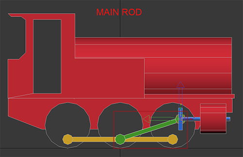
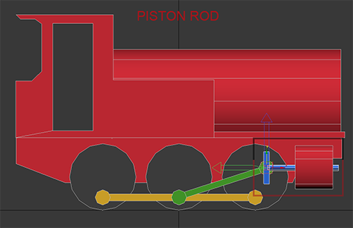
- Main Rod and Piston Rod share the same origin; the pivot point where the Piston Rod and Main Rod are connected (aka Crosshead Wristpin).
We always start with the Piston Rod in the centre of it's travel, and the Coupling Rod centred in either the lowest point in rotation (as shown in the images below). This will dictate the correct length for the Main Rod.
- MeshUri: Path of the file that contains the mesh of the rod.
- PositionX, PositionY, PositionZ: Coordinate value depending on the axis that has been indicated.
- RotationX: Represents the degrees of rotation on the X-axis.
Each animation is made up of eight frames ranging from 0 to 1. Each frame rotates the wheels 45 degrees clockwise.
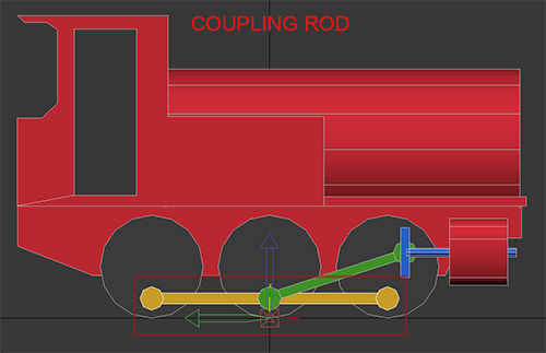
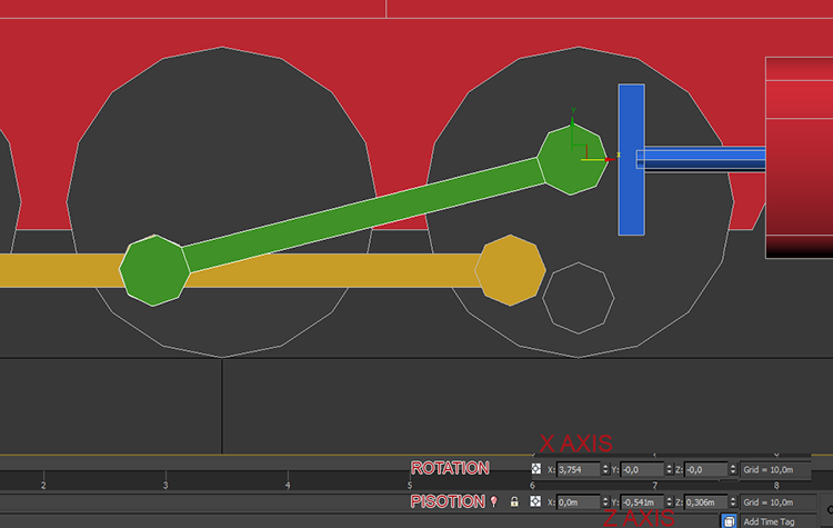
We will start animating the coupling rod. The first thing is to turn the central wheel clockwise 45 degrees by rotating on the X-axis, and then move the coupling rod to coincide with the point of attachment of the wheel.
Once we have the rod in position, we must write down the positions on the Y-axis and Z-axis, which are the values that we have to enter in the second frame of the animation of the coupling rod in the .trainunit asset.
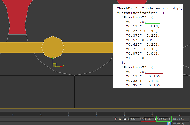
The axes can change according to the 3d modeling program we are using, but the positions will always be the same.
Also, see that position Z has the a negative symbol in the .trainunit asset.
We will keep moving the coupling rod in the same way until we reach the fifth frame that represents half of the animation, where we just need to change the sign of the remaining frames on the Z-axis and repeat the values of the Y-axis frames.
The piston rod is the easiest animation since the position on the Y-axis does not vary and only moves along the Z-axis. Also, the position on the Z-axis coincides with the position of the main rod on the same axis.
For the main rod, we must do the same as with the coupling rod; we move it until the end coincides with the point of union with the coupling rod.
When we have finished the animation, we must put the rods in position 0,0,0, now and we can export them.